
The next ULCSs will be Suezmax
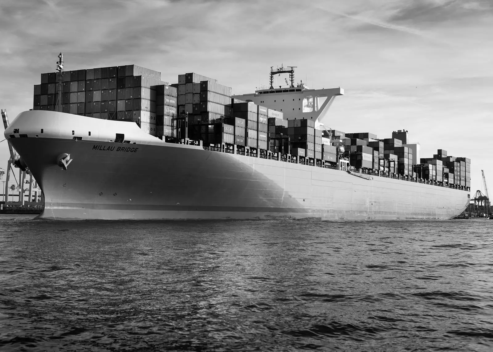
The maximum capacity of container ships has grown quite substantially in the last couple of years. After an initial order for twenty 18,200 teu ULCS in 2011, today more than 100 vessels of this size or with even higher capacity are on order or in operation.
ULCS promise to reduce slot costs due to the “economy of scale” factor and most liner companies engaged on the Far East – North Europe trade are keen to operate this size of vessel in order to catch up with the prime movers, which have enjoyed the expected slot-cost advantages for some time now.
However, some analysts have argued that we have already seen the maximum size of ULCS. These concerns were apparently fuelled by concerns about the stability of freight volume growth, the need to utilize the increasing numbers of ULCS as well as the increasing infrastructure investment costs to allow ports and terminals to handle ULCS.
Nevertheless, the ULCS size is expected to grow further, albeit at a more moderate rate than in the last decade. DNV GL has studied possible options for further increasing ULCS capacity with a focus on two areas:
- A possible increase in the transport efficiency (needed propulsion power per teu) of larger ULCS, with increased length, beam and draft for an assumed operating profile and for a range of homogeneous container weights, also considering typical infrastructural limitations imposed by seaways and ports;
- The structural feasibility of possible future designs.
Transport efficiency
Twenty-one variants of possible future ULCS designs with different lengths, beams and drafts have been analysed:
- Three different lengths – the present 24 bays, 26 bays and 28 bays;
- Three different beams the present 23 rows, 24 rows and 25 rows;
- Three different draught conditions – 15m, 16m and 17m.
For all variants, 12 tiers of containers in the hold and 11 tiers on deck were considered, corresponding to a ship depth of about 33m.
The following parameters were then analysed for all variants:
- Nominal container intake;
- Deadweight at draft conditions 15m, 16m and 17m;
- Lightship weight, corrected to take account of the results of the structural feasibility study;
- Main engine power demand for a speed range from 12kn to 21kn.
Further, for each of the designs, the possible loading capacity with a homogeneous intake of 8t, 10t, 12t, 14t and 16t per teu has been calculated, initially based on the available slots and deadweight. It was then checked whether the resulting loading condition would provide sufficient minimum stability. In cases where this was not achieved, the amount of ballast water needed to achieve a minimum GM of 0.6m was calculated. If the remaining available deadweight was not sufficient to load the required amount of ballast water, the corresponding number of containers was virtually replaced with ballast water.
An average required main engine power demand for each of the variants was then calculated based on an operating profile with an assumed speed distribution. In the next step, the average required main engine power demand per teu for each of the considered homogeneous loading conditions was derived.
Finally, the results were normalized and the difference in percentage was calculated for all variants in relation to the selected “base case” – the design with 24 bays and 23 rows at 16m draft. The results are shown in table 1.
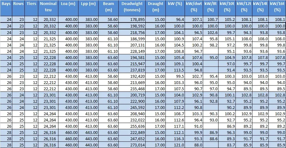
From this analysis it can be concluded that:
- Increasing the draft improves the transport efficiency of all variants for most homogeneous loading conditions
- Increasing the beam by one or two rows but maintaining the length only improves the transport efficiency for the condition with low homogeneous container weight
- Increasing the length by one hold (two bays) but maintaining a beam of 23 rows improves transport efficiency by about 5% for all loading conditions. Increasing the beam in addition increases the capacity but has no positive impact on transport efficiency
- Increasing the length by two holds (28 bays in total) in connection with increasing the beam to 25 rows would increase transport efficiency by about 8-11% depending on the average weight of the containers
Infrastructure limitations
Most container ports in Asia do not impose any restrictions on ULCS dimensions. It is mainly ports in Europe that have limitations, mainly due to the fact that some of them are located in tidal waters at the mouth of, or even many miles up, a river. A maximum length restriction of 400m is nowadays imposed in several ports in Northern Europe.
The port of Hamburg seems to be in a particularly challenging position here. However, plans to enlarge the available turning basin are expected to be implemented by 2017.
Furthermore, it is believed that ULCS with a length of up to 430m which are specifically prepared for efficient manoeuvring (e.g. with sufficient bow/stern thruster power or twin propeller propulsion, strong and sufficient tug pushing areas and bollards/checks for towing lines, etc.) could be handled in areas where the ship length is currently limited to 400m.
Several North European ports also have a beam and/or draft restriction. The number of ports which can serve as the final loading or first discharge port is assumed to decrease if ULCS dimensions increase in the future. This will impose limitations on the set-up of networks/possible sequence of port calls for ULCS, but will probably not stop the growth in ship size.
The present common maximum draft for ULCS designed for the Far East – North Europe trade is around 16m, which could be utilized at least for the final loading and first discharge port.
It is understood that the Suez Canal Authority plans to increase the water depth in the Canal from 66 feet to 72 feet: however no detailed information can be retrieved with regard to the schedule and how this will impact the allowable beam/draft matrix.
Current Suez Canal limits allow passage for ships with a beam of up to 59m beam and a draft of up to 17m. Increasing the draft by about 1m results in an increase of roughly 20,000dwt with the same length and beam. This reduces the required average propulsion power per teu by roughly 6% for heavier containers but is slightly disadvantageous for lighter boxes.
Wider vessels could face limitations on their maximum draft. However, whether or not this leads to a real limitation for the owners depends very much on the current loading condition. When passing through the Suez Canal, vessels might have a somewhat lower draft, as they had in the final loading port, due to the fuel oil consumed during the voyage.
Another limitation on the infrastructure side is the available shore crane technology in the ports along the trade route, with regard to both the outreach of the cranes and the height of the boom, which may limit the number of tiers that can be carried on the deck of a ULCS.
Unfortunately, it is not easy to obtain a detailed overview from public sources. However, it is understood that most ports on the Far East – North Europe trade have upgraded their gantry cranes in the meantime, so that vessels with up to 25 rows across can be served. Nevertheless, in some ports crane height may still be a factor limiting the number of tiers that can be stowed on deck, in particular when considering a design with a depth of around 33 m.
Structural feasibility
For all the design variants given in table 1, a structural analysis of the mid-ship section was carried out in order to check the section modulus and whether the vessels could be designed and built in line with the current design principles/structural arrangements, materials and technologies.
The maximum plate thickness considered was 90mm of steel with a yield strength of 460N/mm2 in the deck area. In the bottom area the aim was not to use steel with a higher strength than 355N/mm2.
The still-water and wave-bending moments which need to be considered for the strength analysis always have a linear relationship with the ship’s breadth and a quadratic relationship with the ship’s length. Obviously, due to this physical relationship with the vertical bending moment, increasing the container capacity by an additional bay affects the steel weight much more than by introducing an additional row.
Consequently, for the longer variants with 26 bays, considerably more steel had to be placed in the upper deck area to fulfil the necessary section modulus requirement and this increased the steel weight and building costs. However, this was not sufficient for the ultra-long variants with 28 bays and their structural arrangement had to be modified in the deck area. A second “strength coaming” on top of the sheer strake had to be introduced to fulfil the necessary section modulus requirement.
Consequently, particularly for the variant with strength coaming, the neutral axis of the cross-section was shifted upwards and resulted in higher hull girder stresses in way of the double bottom. To maintain the use of steel with a yield strength of 355 N/mm2 in the bottom area, the plate thicknesses had to be increased here too.
To cater for additional stress components, such as double bottom bending, which are normally analysed during later stages of the design process using FEM-based methods, the section modulus at the outer bottom has been dimensioned with a minimum margin of 13% for all variants.
One option to reduce the weight of the longitudinal structures by about 4% would be to introduce steel with a yield strength of 390 N/mm2 in the outer bottom in the mid-ship area. However, this introduces other challenges and would require further investigation. Table 6 shows the described effects for selected variants. Based on the mid-ship cross-sectional analysis, the deadweight of the variants in the parametric analysis discussed above was adapted.
When studying possible variations in draft, it was found that increasing the scantling draft from today’s 16 m to a possible future 17m only has a marginal impact on the steel structures.
Conclusion
The next generation of ULCS can be designed, built and operated without major changes to the design concept/structural arrangement of present large container ships.
It appears likely that the beam will be increased to 24 rows in the next step, increasing the nominal capacity by roughly 1,000 teu while keeping the fuel costs per teu almost unchanged. By increasing the maximum draft of the 24-row-wide ULCS from 16m to 17m, the deadweight capacity can be increased by about 10%, which increases the fuel efficiency – in particular for heavier containers.
If an even higher nominal capacity is required than a lengthening of the vessel by one cargo hold (for an extra 26 bays) would result in a teu intake of about 23,300, with fuel costs per teu reduced by roughly 4.5%.
The infrastructure of seaways and ports is not believed to impose barriers to this development that cannot be handled. By increasing the beam to 25 rows and length to 26 bays, the capacity of a ULCS could reach 26,300 teu. However, such a design would be restricted from entering a number of ports and would not be able to pass through the Suez Canal with its current restrictions in a fully laden state. This would also require a new structural design concept, introducing “strength coaming” on top of the sheer strake. That is why it is not likely that such a size of vessel will be ordered in the near future, even though it would promise another 3.5% reduction in fuel costs per teu.
Related Articles
 PROPULSION
 GENERAL NEWS
 HYDROGEN