


New turbocharger cut out system ensures efficiency of MAN 10.6 engines
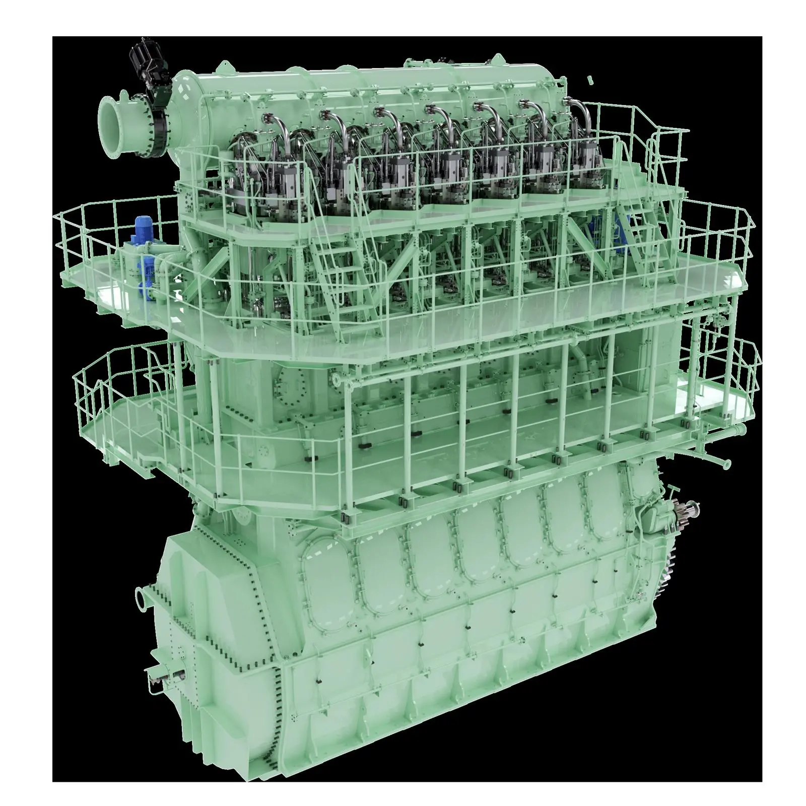
Lars Ascanius, Senior Manager Design Small Bore, and Henrik Møller Hansen, Senior Manager, Design Large Bore, at MAN Energy Solutions discussed the development of the 10.6 engine and also the latest exhaust gas recirculation (EGR) developments at CIMAC, highlighting that they are some of the steps the company is taking to future-proof its engines.
Currently the new large 2-stroke 10.6 engine types that have been developed by MAN are based on the S50ME-C9.7 and S60ME-C10.5 engine and include 50, 60, 80 and 95cm bore. The aim is to continue boosting the efficiency of MAN’s single-fuel engines which currently make up about half of its engine sales. The changes made to create the 10.6 version include the development of a sequential fuel injection system and for the G95 version a new turbocharger cut out system.
Sequential fuel injection
The engines feature a new sequential fuel injection system which is based on MAN’s existing technology but provides for flexibility in the injector sequences of each cylinder to enable performance optimisation and NOx formation management. The high engine efficiency of the new engine necessitated a NOx solution to ensure the engine remained Tier II compliant. The production of NOx emissions is related to fuel consumption and the mechanical and thermal load of the combustion chamber. Each of these parameters is inter-related, and the sequential fuel injection optimisation involves carefully timed sequencing of each injector. The concept is able to reduce NOx formation, and when combined with higher maximum cylinder pressures, fuel oil consumption is also reduced, as it only results in a small fuel oil consumption penalty.
The process is electronically controlled, with fuel booster injection valves hydraulically operated and controlled by window injection valve actuation. This ensures precise control for the system as the fuel enters via pipes to a sleeve in the cylinder cover. A hydraulic cylinder unit sequential replaces the existing hydraulic cylinder unit as it no longer requires a booster, and the new unit takes up half the space of previous units.
The exhaust valves and actuators are similar to those in existing hydraulic cylinder units and fuel injection valve actuators, but they are now located on the manoeuvring side of the cylinder cover rather than being placed on the baseplate.
The overall increased maximum combustion pressure of the 10.6 has led to reinforcement of both moving and structural engine parts, but this has been achieved with minimal change to engine room layout. The cylinder distance and height of interfaces are maintained.
Turbocharger cut out system
In addition to the sequential fuel injection system, the 95-bore variant has an advanced version of the manufacturer’s traditional turbocharger cut out system which involves taking one turbocharger out of operation at low load. This ensures optimal efficiency of the available turbochargers, and dynamic control ensures seamless changeover.
An exhaust gas bypass is typically used to control scavenge air pressure by matching the turbochargers to a specific pressure at 100% load with an open bypass to reduce turbocharger power. This is analogous to having a lower efficiency turbocharger temporarily, with scavenge air pressure returning to higher levels when the bypass is again closed.
In contrast, the sequential turbocharging system developed by MAN instead cuts out one of the turbochargers at low load and smoothly cut it back in at high load (up to Four turbochargers can be installed on each engine) so that the active turbochargers always receive the full exhaust gas power. This avoids the reduction in scavenging quality at high load that would have occurred with the traditional bypass system.
The turbocharger to be cut out is sized according to the desired magnitude of the effect on the scavenge air pressure, and is typically smaller than the other turbochargers installed. Cutting a turbocharger can restrict engine load below 100% as the active turbochargers are unable to handle all the exhaust gas, so cutting only occurs between 50 and 75% engine load so efficiency isn’t impeded.
The cut-out control MAN has developed involves one butterfly valve at the compressor outlet and one at the turbine inlet. These valves can complete their designed trajectories in 1-2 seconds. The control sequence for their operation has been integrated into the engine control system and ensures that compressor surging doesn’t occur. It also prevents excessive pressure drop during the cutting-in and cutting-out transition phases.
Engine testing has confirmed that the positive effects from the exhaust gas bypass are preserved without the efficiency of the turbochargers being impacted at high load. MAN states that the SFOC reduction is obtained by applying sequential fuel injection and sequential turbocharger combined with the increased maximum combustion pressure. This makes it possible to improve the fuel consumption by up to 4 g/kWh for S50ME-C10.6, up to 6 g/kWh for S60ME-C10.6, up to 3 g/kWh for G80ME-C10.6 and up to 3 g/kWh for G95ME-C10.6. The larger reduction for the S60ME-C10.6 engine is the result of the engine’s larger increase of the maximum combustion pressure.
Mechanical changes
Some mechanical changes were made for the S60ME-C10.6 engine due to the maximum combustion pressure increase achieved for the engine. The platform used for its development was the S60ME-C10.5, but moving and structural parts were reinforced to maintain the desired safety margin against fatigue and bearing failure. These reinforcements didn’t, however, result in significant changes to engine room layout.
Main bearing size remains unchanged, as the main bearing zero is now introduced on the fore end of the engine to avoid having a bearing edge load that is too high. The crankpin bearing has increased diameter and width, and main bearing support side machining has now been introduced, along with crosshead bearing changed from white metal to tin-aluminium.
A main bearing zero has been introduced to avoid excessive edge load and to prevent oil film thickness becoming too thin on main bearing No. 1. The main bearing zero has been located ahead of the axial and torsional vibration damper. The crankshaft inclination has also been reduced in main bearing No. 1.
While the mechanical changes made to the S60ME-C10.6 engine increase its weight by around 4.6%, the greater efficiency of the engine results in fuel saving of up to -6 g/kWh.
EGR developments
MAN has made developments on its EGR system to optimise performance, reliability and cost, noting that increased environmental awareness, expansion of emission control areas as well as increased focus on operational aspects of low or zero sulphur fuels for dual fuel engines call for a simple and reliable emission reduction system. Initially standard in the ME-GA engine, they will also be introduced on other engine types, including the 10.6.
Oxygen levels are integral to the control of any EGR system, and the sensor cabinet unit typically has a relatively large footprint, so MAN has developed a simpler system. A new oxygen sensor unit is now standard for all EGR systems, and it is located closer to the oxygen probe to ensure faster response times as well as simpler operation.
MAN has also designed a low-speed blower with a standard industrial electric motor that operates below 3,600 rpm (60 Hz). The detailed design was developed in partnership with blower manufacturer.
A new exhaust gas recirculation cooler has been developed as the Tier III solution that is a stainless steel version of seawater box coolers. This provides increased reliability and durability. The detailed design was developed in partnership with cooler manufacturer Kelvion and includes bent tubes as a replacement for a reversing chamber. The tubes are supported in a way that enables free movement of the side plates during different levels of thermal expansion.
A new and simplified water handling system has also been developed that consists of an on-engine buffer tank, treated water supply unit and related piping located on-engine. This significantly simplifies engine room installation, says MAN.
With these developments, and the latest 10.6 engines, MAN says it is pursuing the best possible efficiency and the lowest possible carbon footprint for the industry.
Related Articles
 2-STROKE & 4-STROKE
 2-STROKE & 4-STROKE
 2-STROKE & 4-STROKE