


Integrated propulsion design drives efficiency
The drive for greater efficiency – driven by economics – goes hand in hand with the need to cut emissions – driven by legislation. In current times, where there is a real need to cut costs as much as possible at the same time as installing often-expensive means of improving environmental performance, any gain in efficiency can pay dividends. Cutting fuel use automatically leads to lower cost, and lower emissions, so any gain is welcome.
Under earlier examples of exhaust emissions limits, cuts in harmful gases (i.e. oxides of nitrogen, or NOx, whichis what has been the historical subject of legislation) resulted almost entirely from modifications to the engine. The limits of what can be done in this respect have effectively been reached by IMO Tier II. So Tier III, and other new legislation designed to reduce emissions of sulphur oxides, carbon and particulate matter (including the so-called ‘black carbon’) demand additional costs, either for extra on-board equipment or for more costly fuel, or a combination of both. So reductions in fuel use, which go some way towards offsetting these additional costs, are even more beneficial.
This is leading ship designers and builders to look beyond the engine for gains in fuel economy. For several years, there has been talk of integrated propulsion systems and a more holistic approach to ship design. But the industry has held back, for many valid reasons, until now. Those operators who have looked at matching the engine to the propeller, and matching the hull form to the hydrodynamics of the propeller, and, indeed, concentrated on getting the trim and loading of the ship to its most efficient point, are now reaping the benefits.
One must bear in mind that many of the ships afloat, and even many recent builds whose basic design dates back several years, are optimised for significantly higher speeds than are common today, thanks to the need to save fuel making the practice of ‘slow steaming’ much more common. Engines which were designed to operate near to their maximum continuous rating (MCR) are now operated at a far lower load, so many are being modified – mainly by changes to the turbochargers to increase part load efficiency so that optimum fuel economy is achieved at lower ratings. And because ships are travelling – and engines turning – slower, they are able to make use of greater efficiencies from larger-diameter propellers, optimised for lower speeds. When large propellers are combined with extra-long stroke low speed engines, fuel savings can be impressive; and combined with other new developments which increase ship efficiency, these savings can actually make it economically viable to replace older tonnage with new designs, the saving in operating costs and the enhanced attractiveness in the charter market meaning that the capital cost involved in a high-efficiency new build can be amortised within a reasonable period.
Unlocking integrated design
As a supplier of all elements of the propulsion system, as well as offering ship design, Wärtsilä is able to take a holistic approach to propeller design and has recently launched higher-efficiency propellers in both fixed pitch and controllable pitch form.
Computational fluid dynamics (CFD) is the key to the latest fixed pitch propellers, known as the FPP Opti design, from Wärtsilä. Norbert Bulten, general manager hydrodynamics, explains that this allows designers to work from the outset using full-scale numerical models rather than scaling up from the semi-empirical data obtained from tank tests, as before.
“The conventional maritime industry approach is to optimise hull resistance and propeller performance separately,” says Bulten. “The bare hull resistance is minimised by the naval architect, and the propeller thrust is maximised for a given power by the propeller designer. Once both designs are combined (ship + propeller) the actual performance of the system is found. Due to the action of the propeller, the actual bare hull resistance increases, which is often considered as being an inevitable loss of overall performance. Modern numerical flow simulations specifically address this issue.”
Wärtsilä’s new design has been developed at the company’s Technology and Service Centre in the Netherlands, and is the result of highly experienced design engineers having access to the very latest and most sophisticated software and analysis tools. CFD calculations analyse not only the propeller performance but most importantly also, the interaction between the propeller and hull. This provides extremely accurate information, which is used to achieve design and parametric optimisation.
“Wärtsilä has more than 100 years of experience in developing high quality propeller solutions. To this huge knowledge resource we have now been able to add a highly sophisticated state-of-the-art design approach that is unmatched in the industry. The hull and the propeller, and the interaction between the two, can both now be taken into account during the design process. The result is a higher level of efficiency and lower operating costs,” says Arto Lehtinen, vice president, propulsion, Wärtsilä Ship Power.
Calculations show that the FPP Opti propeller approach can be expected to yield up to 4% savings in overall fuel consumption.
Several different steps are involved in the Opti design philosophy. A full scale bare hull calculation determines hull resistance and wake field, while full-scale B-series polynomials are employed to select the optimum propeller diameter. The so-called B-series figures are based on a large set of model scale propeller performance measurements that date back as far as the immediate post-WW2 period. Although current realisation is that these predictions may differ significantly from the actual full-scale performance, the B series is still considered to offer a good starting point.
The standard design tools, combined with several decades of experience gained by Wärtsilä’s propeller design teams, allow CFD methods to be applied to evaluating the full-scale propeller performance in open water. CFD then enables a full scale propulsion calculation involving both hull and propeller, which will determine the interaction factors and thus the propeller performance in behind-ship condition. Further analysis can be applied in order to evaluate the effects of geometric variations of the propeller. Having reached this stage, then a final model scale test can be carried out as part of the Opti design process to prove the calculations.
Bulten explains that: “During the past two decades, the development of numerical methods has made huge progress. Nowadays, the effects of viscous flow can be taken into account for engineering applications, which means that accurate bare hull resistance predictions and propeller open water performance calculations are feasible. Based on current technology, the viscous flow simulations – also denoted as RANS (Reynolds-Averaged Navier-Stokes) – can take the effects of the free surface along the hull, and the dynamic sinkage and trim of the vessel into account. Moreover, the accuracy of the calculations can compete with the accuracy of the model scale resistance measurements. Now that confidence in the numerical methods has been established, the step towards actual full scale geometries can be made. In this way the need for the semi-empirical extrapolation methods, as used in the model tests, will diminish.”
He continues: “The added value of the numerical simulations is found in the extensive options of flow visualisation and post-processing. With these means of data analysis, it is possible to get new insights on the actual occurring flow phenomena, such as the interaction phenomena. It is also possible to determine the contribution of drag on the different components and appendages on the hull so as to get an indication of their contribution to the total resistance. The value of the numerical simulations is, to a large extent, based on the achieved accuracy of the simulations. Validation of the methods is, therefore, one of the key elements in the implementation process of CFD. At Wärtsilä, a multi-year project on the method development for propeller performance predictions, thruster load determination, and ship hull resistance calculations, among others, has been executed.”
Wärtsilä says it continues to develop solutions that save energy and improve the efficiency of its FP ship propellers. These include the Tip Rake Concept featuring an extended tip, smoothly curved to the pressure side of the blade with optimised geometrical parameters developed to achieve efficiency improvements, lower pressure pulse levels, and a quieter propeller.
The Wärtsilä EnergoProFin is a propeller cap with fins that rotates together with the propeller, which can be of any make. By weakening the hub vortex, resistance is decreased and propulsion thrust is increased, resulting in fuel savings of up to 5%.
Energopac is Wärtsilä’s optimised propulsion and manoeuvring solution that reduces fuel consumption by integrating the propeller and rudder designs. It is claimed to be fully optimised for energy efficiency without compromising either manoeuvrability or comfort levels.
The company’s recently-introduced controllable pitch solution is based on its established E-hub, but developed further for higher efficiency and reduced environmental impact. It too employs CFD techniques to follow a systems engineering approach with integration of the propeller and hub with modern hydraulics and propulsion controls. Analysis of interaction between the propeller and hull, made possible through the use of CFD, combines with propeller performance calculations to achieve optimum propulsion efficiency. The hub design allows the use of environmentally acceptable lubricants (EALs) and is said to be particularly well suited to larger vessels with dynamic positioning (DP) capabilities.
Ducts for efficiency
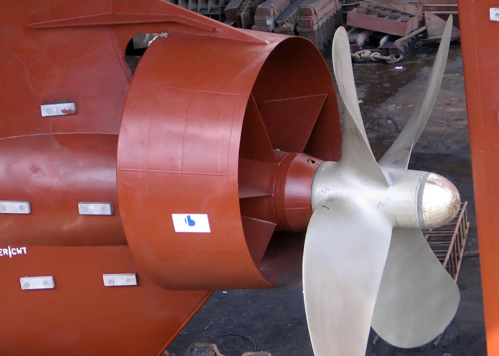
German company Becker Marine Systems has enjoyed considerable success with its Mewis Duct, described as a power-saving device developed for full-form slower ships that provides significant fuel savings at a given speed.
It consists of two fixed elements: a hull-mounted duct positioned ahead of the propeller; while inside the duct is an integral fin system. The duct straightens and accelerates the hull wake into the propeller and produces an element of thrust. The fin system provides a pre-swirl to the ship wake which reduces losses in propeller slipstream, resulting in an increase in propeller thrust at given propulsive power. Both effects are said to contribute to each other.
The system has proved particularly effective for large ships with high block coefficient, such as tankers and bulk carriers, travelling at speeds below about 20 knots. Such ships often have low propulsion efficiency, as a result of bad wake field and high propeller loading. The Mewis Duct is said to harmonise and stabilise the flow, and generate a pre-swirl to reduce rotational losses in the propeller slipstream, thus enabling the propeller to operate in improved inflow conditions.
According to Becker, the integrated fins have a stator effect by generating a pre-swirl counter to the direction of propeller operation. This generates more thrust. The fins are asymmetrically profiled and arranged to generate a homogenous flow distribution. Achievable savings depend on propeller thrust loading, ship draught and speed, but are typically in the range of 3% to 8%. The Mewis Duct can be designed into a new build, or retrofitted to existing ships – the company says it takes about four days to fit, and payback can be achieved within one year.
Further propulsion improvement can be achieved if other aspects of hydrodynamic performance ca be taken into account, for example by combining a Mewis Duct with a corresponding Becker Rudder. This can increase overall efficiency by means of wake field optimisation and lower rudder resistance with improved manoeuvring performance.
A similar system to the Mewis Duct is offered by Becker Marine Systems for faster ships with speeds above 18 knots. The efficiency of the Mewis Duct decreases above this speed, so the company has introduced its Twisted Fin for fater large ships such as container vessels. The Twisted Fin, like the Mewis Duct, has no movable parts, is installed in front of the propeller and generates a pre-swirl. The nozzle ring is smaller than that of the Becker Mewis Duct, and has a flat profile for reduced drag. Whereas the fins of the Mewis Duct are contained within the nozzle, on the Twisted Fin they extend outwards, and are fitted with anti-swirl end caps beyond the nozzle, intended to prevent cavitation at the ends of the fins. The small nozzle ring is said to generate thrust, provide stability to the fins and reduce vibrations.
CFD calculations, model tests and full scale operation suggest fuel savings around 3% for container ships, and as with the Mewis Duct, efficiency gains can be achieved with the combination of a Becker Twisted Fin and the TLKSR rudder.
Propeller and rudder integration
Rolls-Royce has applied similar principles to its Promas system, which integrates the propeller and rudder designs in order to achieve reduced fuel consumption. As well as the Promas, designed for newbuild ships, the company offers its Promas Lite retrofit system as an upgrade for vessels already in service. The upgrade consists of three main components: a bulb which is attached to the forward edge of the rudder; a hubcap which is bolted to the rear of the propeller; and a set of redesigned propeller blades.
Again, CFD technology is used by the Rolls-Royce Hydrodynamic Research Centre to ensure that each design is matched to the hull and specified operating profile. Benefits claimed include lower fuel consumption – as much as 20% can be saved if the existing propeller is not optimised to the ship’s current operational profile – with corresponding reductions in environmental impact. With the advances in propeller design, it is known that propeller blade changes, or the fitting of new propellers, can have a significant effect on propulsive efficiency, fuel consumption and, therefore, emissions. Promas helps to maximise these improvements at only a small increase in cost, according to Rolls-Royce, as the propeller and rudder are treated as a complete system.
Payback too depends on the operating profile, but Rolls-Royce says that a period of less than two years is typical. Promas Lite can usually be fitted as part of a routine dry docking, and, as there are no complex mechanical features, there should not be any additional maintenance requirement. As engine loading is reduced, there is potential for saving on maintenance due to reduced wear and lower lube oil consumption
According to Rolls-Royce, as well as improving efficiency, manoeuvrability can benefit from the optimised rudder performance. Although the best results are achieved on bulky single screw vessels with a high block coefficient, Promas Lite has been installed on several twin screw passenger vessels, significantly reducing fuel consumption and emissions.
The company describes the action of the system thus: behind a normal propeller hub there is a strong low pressure vortex (hub vortex) that acts on the propeller hub, increasing drag and reducing propeller thrust. A special hubcap is fitted to the propeller which streamlines the flow onto a bulb that is added to the rudder, effectively reducing flow separation immediately after the propeller. The result is an increase in propeller thrust, as previously wasted energy is recovered from the flow.
The bulb on the rudder also streamlines the flow aft of the rudder, further reducing drag. The hubcap is mounted outside of the propeller hub and acts purely as a hydrodynamic fairing. No special hub design is needed, thus cost and technical complexity is kept to a minimum. Promas features a twisted rudder design to yield further improvements in efficiency and manoeuvrability.
Related Articles
 PROPULSION
 GENERAL NEWS
 GENERAL NEWS