



The implications of ice class on two-stroke ship propulsion
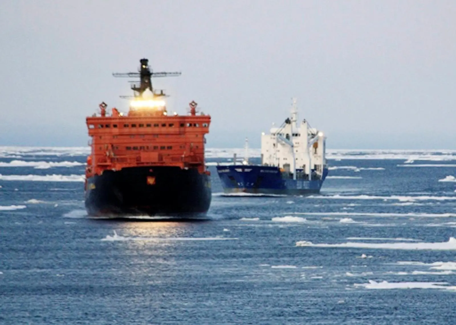
Ships with ice class have a strengthened hull to enable them to navigate through sea ice. Depending on the class, sea chests, i.e. the openings in the hull for seawater intake, have to be properly arranged in order to avoid blocking up with ice. Most of the stronger classes require several forms of rudder and propeller protection, and strengthened propeller tips are often required. Different ice classes and types exist, depending on the classification societies, but the most often ice class referred to is the Finnish-Swedish ice class.
Low temperatures impose restrictions on start-up procedures of two-stroke engines, and MAN B&W recommends that In order to protect the engine against cold corrosion attacks on the cylinder liners, certain temperature restrictions and load-up procedures have to be considered.
The recommended start of engine at normal engine load operation varies according to whether a fixed pitch (FP) or controllable pitch (CP) propeller is employed. With FP propellers, a normal minimum engine jacket water temperature of 50ºC is recommended before the engine is started and run up gradually to 80%, and slowly from 80% to 90% of the specified maximum continuous rating (SMCR) speed for another 30 minutes For running-up between 90% and 100% of SMCR rpm, it is recommended that the speed be increased slowly over a period of 60 minutes.
In the case of CP propellers, a minimum engine jacket water temperature of 50°C is recommended before the engine may be started and run up gradually up to 50%, and then slowly from 50% to 75% of SMCR load over 30 minutes. For running-up between 75% and 100% of SMCR power, it is recommended that the load be increased slowly over a period of 60 minutes.
When the engine is to be started under normal low engine load conditions (e.g. ultra-slow steaming) at low temperatures, a different procedure should be employed. For engines running most of the time at 10% to 40% engine low load, an extra slow load-up procedure is recommended compared with the load-up procedures described above.
During short stays in ports (i.e. less than 4-5 days), it is recommended to keep the engine preheated, the purpose being to prevent temperature variations in the engine structure and corresponding variations in thermal expansions, and thus the risk of leakages.
MAN B&W has further design recommendations for its two-stroke main engines when operating at extremely low air temperature. This is because when a standard ambient temperature-matched main engine operates under Arctic conditions with low turbocharger air intake temperatures, the air density will be too high. As a result, the scavenge air pressure, the compression pressure and the maximum firing pressure will also be too high.
In order to prevent excessive pressures under low ambient air temperature conditions, the turbocharger air inlet temperature should be kept as high as possible. Furthermore, the scavenge air coolant (cooling water) temperature should be kept as low as possible and/or the engine power in service should be reduced.
Foe extreme low temperature operation, MAN B&W recommends a load-dependent exhaust gas bypass system, developed by the company for Arctic applications. With this system, part of the exhaust gas bypasses the turbine section of the turbocharger, giving less energy to the compressor, thus reducing the air supply and scavenge air pressure to the engine. Most of the engines in the MAN B&W two-stroke portfolio are capable of meeting the Finnish-Swedish ice class notation 1C, 1B, 1A, and even 1A super or similar, without modification. This means that the standard thrust bearings for most of the MAN B&W two-stroke engines are sufficient.
A CP propeller will often prove advantageous for high ice classed ships. However, because of the high efficiency and simplicity, a FP propeller may often be preferred for low ice classes. When a ship with FP propeller is operating in normal sea service, it will in general be operating around the design propeller curve 6, as shown in the standard load diagram.
For ships with special operating conditions, like occasionally operating in thick ice, involving a degree of ice ramming, it would be an advantage during normal operation conditions to be able to operate the propeller/main engine as much as possible close to line 6, but in ice situations with heavy running propeller inside the torque/speed limit, line 4.
For ships occasionally operating in heavy ice, the increase of the operating speed range between line 6 and line 4 of the standard load diagram may be carried out as shown in the extended load diagram for speed derated engine with increased light running.
When a ship with CP propeller is operating under ice ramming conditions, the running point on the combinatory curve of the CP propeller (could be on line 6) will suddenly change because of the ice ramming and move to the left in the load diagram. The reason is that there is some reaction time in changing the CP propeller pitch. For such running conditions, the extended load diagram may be useful for the main engine operation.
Normally, and this is also valid for low ice classes, FP propellers are installed because of their simplicity and high efficiency. The propellers are cast in one block, and therefore the position of the blades, and hence the propeller pitch, is once and for all fixed with a given pitch that cannot be changed in operation. This means that when operating in, for example heavy weather and ice, the propeller performance curve will be very heavy (reduced speed for same power). Compared to the FP propeller, for the CP propeller, the position of the blades, and thereby the propeller pitch, can be controlled to avoid heavy running and overload of the main engine. Therefore, CP propellers can, with advantage, be applied both for moderate ice classes as well as for very strong ice classes.
When sailing in ice with a bulk carrier or a tanker, the ship has to be ice classed for the given operating need of trading in coastal states with seasonal or year round ice-covered seas. Besides the safety of the hull structure under operation in ice, the minimum required propulsion power for breaking the ice has to be met.
For existing ships with conventional main engines, such as average bulk carriers and tankers built before 2007, the minimum power demand, according to the formulae of the Finnish-Swedish ice classed ships, the lower ice classes, 1B and 1C, can – power-wise – generally be met.
As far as future ship designs, with more modern main engines, the Finnish-Swedish ice class formula states that required installed propulsion power is inversely proportional to the propeller diameter, i.e. the larger the propeller is, the lower the power requirement. Future ships may be delivered with a high-efficiency propeller, typically with a 10-12% larger propeller diameter. This means a lower optimum propeller speed, and this can be matched to an ultra-long-stroke MAN B&W two-stroke G-type main engine, resulting an about 5%-8% higher total efficiency.
A ship with high ice class imposes a relatively high SMCR power demand, owing to the extra power margin needed for sailing in ice. As the ship will be operating in ice-free areas for the majority of the time, the main engine in normal sea service may operate at low load. Therefore it may be advantageous to optimise the engine for low load operation.
NOx regulations place a limit on the SFOC on two-stroke engines. In general, NOx emissions will increase if SFOC is decreased and vice versa. In the standard configuration, the engines are optimised close to the IMO NOx limit and, therefore, NOx emissions may not be further increased. The IMO NOx limit is given as a weighted average of the NOx emission at 25%, 50%, 75% and 100% load. This relationship can be utilised to tilt the SFOC profile over the load range. This means that SFOC can be reduced at part load or low load at the expense of a higher SFOC in the high-load range without exceeding the IMO NOx limit.
Only high-load optimisation is available for engines with conventional turbochargers of 64% efficiency (rather than the higher 67% efficiency) and non-adjustable maximum firing pressure at part load (e.g. MC engines without VIT). Optimisation of SFOC in the part-load (50-85%) or low-load (25-70%) range requires the application of a tuning method. Furthermore, a turbocharger cut-out method is available for SFOC reduction at part/low load operation.
For ice classed ships where no ice ramming operation is anticipated, the standard diesel-mechanical propulsion systems for merchant ships can be applied, i.e. CP or FP propeller directly coupled to a two-stroke main engine. When ice ramming is involved, a diesel-electric system with CP propeller may be preferable, as the electric motor is better able to handle occasional high torque deviations. The disadvantage of a diesel-electric system is an 11%-12% lower efficiency than a mechanical propulsion system with directly-coupled CP propeller. Therefore, when most operations are in normal sea conditions without ice, mechanical alternatives to the conventional diesel-electric propulsion system might be preferred.
Related Articles
 PROPULSION
 GENERAL NEWS
 GENERAL NEWS