
Solving the clean-up conundrum
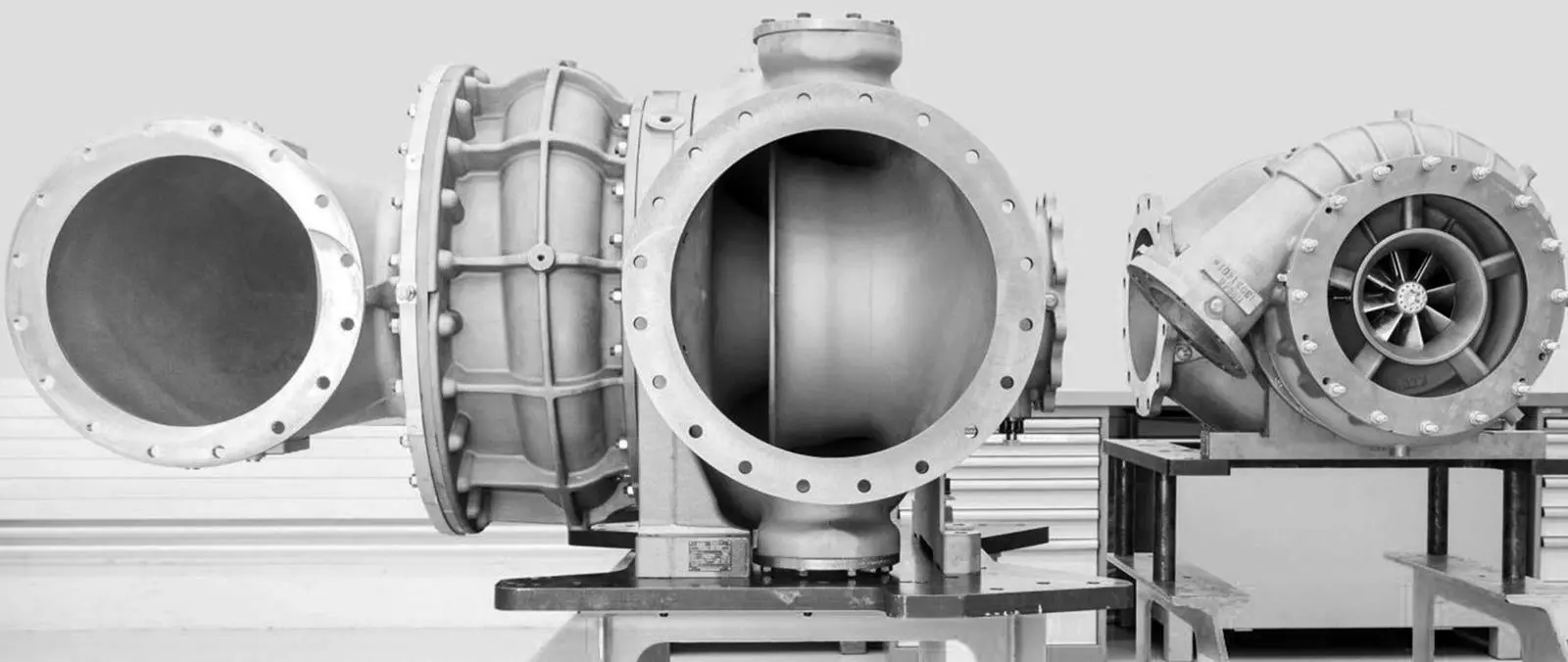
Firstly, as Michael Willmann of ABB Turbocharging points out: “Any step that helps to minimize the engine footprint, such as increasing the power density through the use of higher receiver pressure, is desirable.”
But it’s broader than that: for marine’s medium-speed engines, “concern centres rather more on efficiency and peak pressure”, says two-stage turbocharger development lead for PBST, Sebastian Spengler. Here, it’s not just an enabler for high power densities, it’s also aimed at NOx and SFOC reduction.
However, there’s a conundrum: “A greater mean effective pressure in the engine requires more mass coming through the air intake,” says Johannes Kech of Rolls-Royce’s Power Systems business unit. This doesn’t necessarily sit well with combustion clean up techniques aiming to meet IMO Tier III and EPA Tier 4 NOx requirements (which this year reached the Baltic and North Sea ECAs). All of which puts yet more demand on the turbos.
Take Exhaust Gas Recirculation: this diverts some of the exhaust flow back into the intake manifold, diluting the charge, reducing available oxygen, combustion temperature and NOx formation on the flame front. However, large engines require considerably higher EGR rates to achieve the same NOx reduction level as their smaller automotive counterparts – the fraction sometimes reaching over 50%. Therefore, the EGR can be asking for more while the turbo itself might be feeling the pinch.
Another technique is playing with the timing to change the combustion characteristics: on a Miller cycle, the charge is limited by either late or early intake valve closure. This can be tweaked to reduce the work required by compression, stretch out the intake charge to cool combustion temperatures from NOx-formation levels, and harvest more energy from the cycle.
While a turbo can mitigate the consequent power loss, stronger Miller timing necessary to meet advancing NOx requirements also means “there’s much less time for bringing the air through into the cylinder”, explains Kech.
He adds that even relatively straightforward particulate filters “put a higher back pressure on the exhaust system, so to ensure the exhaust flows out of the cylinder, again you need more pressure on the intake side”.
Initially, EGR, filter pressure and Miller cycle demands were supported through single-stage turbochargers. These are comparatively simple and cost-effective, so they’ve gained a good slice of development: ABB’s product has lifted the pressure ratio ceiling from 6.0 to 6.5, while PBST has been investigating how to move towards 7.0 with package, cost and performance benefits for medium speed and high speed gas engines.
But these single-stage units have shortcomings. While they can deliver emissions savings, above a pressure ratio around 5 or 5.5, “the topological map of the compressor tends to narrow, and in this situation, the engine’s overall performance becomes rather limited”, says Kech. In other words, it can be set up either for a wide speed range or a high boost pressure – but there’s generally a trade-off between the two.
Just adding another TC for increased speeds will fix a number of issues. “A sequential system means starting the engine with one turbocharger: accelerating to a higher power triggers a second, then a third and so on,” he explains.
That in turn allows more boost at low engine speeds and faster transient response. However, sequential turbocharging has a different focus: broad performance maps and greater surge margins remain the highest priority for compressor development. But as these systems still operate within the confines of single-stage TCs, Kech points out “this setup can’t reach the pressure ratios required for emission reduction technologies”.
Instead, the answer lies in two-stage TC arrangements which can push the pressure ratio into double figures. Here, the inlet air is speeded up and compressed, first by one or two low-pressure turbines in parallel, giving it a leg up. It’s then cooled to make it denser before it’s transferred to a high-pressure stage and possibly another intercooler, explains Willmann. However, he adds that the load distribution between the lower and upper stages “influence both the system efficiency and its size”.
That means that for OEMs like Rolls-Royce – currently working on a new two-stage offering for its mtu series 4000 marine four-stroke – the effort is not merely to get the highest peak pressure rise out of the individual turbines. Instead, it’s to tailor their highest efficiency regions to their operating position on the now combined, two-stage compressor map.
But for manufacturers like ABB Turbo and PBST, the focus is adaptability, offering matching combinations between a variety of high and low pressure turbines. Spengler adds that even inside these stages, different fuel type or application requirements can change the arrangement.
Therefore, tailoring each stage isn’t easy. Firstly, “the load split between HP and LP is typically defined by static matching,” he says, with parts like nozzle rings and diffusers being modelled to meet the engine’s most common demand.
Further, operational points outside this area can be so diverse as to require changing the balance. Variable geometries (used onboard MAN’s 51/60 GTS engine) and other devices have their place: Rolls-Royce, for example, is incorporating a valve or flap mechanism to alter the flow with a bypass that allows the LP side to pick up more of the load as speed rises and it also acts as a wastegate to protect the HP side at very high flow rates.
It opens up the possibilities but also creates another level of complexity, and more, “any methods need to be closely linked to the engine control and operation”, adds Spengler.
Still, the (often iterative) matching process may be somewhat eased by further turbine developments.
Radial – centrifugal – designs have been the general go-to choice for single-stage compression. These work by hurling out the gas at an angle: it then flows through the spiral chamber where the velocity gets converted to pressure. While radial units can maintain overall efficiency across the rpm range and deliver a considerable step-up in pressure ratio in one hit, the limits are blade size and impeller stresses from supersonic gas speeds.
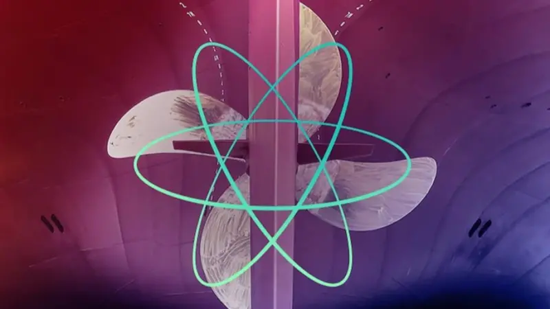
Recently, two-stage solutions have opened the door to axial compressors. These typically have a set of rotating blades – more like propellers – which accelerate the gas directly along the flow path to a stator, which converts it to pressure. They make a better job of handling large volumes than radial types, but two features have held back take up: they don’t yield as big a jump in pressure, and their efficiency isn’t that even, generally rising with speed.
Despite that, axial flow’s characteristics are still attractive for larger four-strokes, and some marine manufacturers may be considering them for the initial, low-pressure stage.
For example, although Kech underlines Rolls-Royce’s development decisions aren’t set in stone, he says “the advantage of an axial turbine is its low momentum of inertia compared to a radial turbine, achieving higher agility”. ABB Turbo also appears to be contemplating their advantages, as Willmann notes: “With increasing airflow, the classical trade-off between radial – high-pressure ratio – and axial – high mass flow – machines may lead to consideration of axial turbines for large-bore marine engines.”
Interestingly, as part of its modular approach, PBST is already offering its new, axial TCT series as its smaller, lighter design makes it suited for the LP turbo in two-stage systems.
However, the HP side “is generally more physically demanding,” says Spengler. Here, radial versions have their advantages, as they have a very robust, well proven and compact design while covering all efficiency requirements. But he adds: “The blade vibration is higher, forces on the bearings are more powerful – and nearly all the components are subject to more stress .”
So it has taken effort. Both Rolls-Royce and PBST have been working on geometry; PBST’s radial TCX has recently benefited from smoothing the internal flow alongside tweaks such as channelling water-cooling toward higher temperature areas and thicker walls in certain regions.
Further, some of the designs also offer ramp-up support: for example, the TCX has a Jet Assist which blows high-pressure air onto the compressor blades, assisting TC acceleration.
Finally, two-stage turbos have enough potential to support all kinds of clean-up technology. “It is a big enabler for Miller timing,” says Spengler: “If you deliver very high pressure to the cylinder, you can afford to lose a bit, and you still have enough power density in the cylinder afterwards. That’s the key.” While there is still a trade-off, tests demonstrate that with a strong Miller cycle, you can drop NOx or SFOC significantly compared to single-stage TCs.
There’s still a world of possibilities. Rolls-Royce’s initial two-stage model for the mtu 4000 marine engine looks likely to have twin LP turbines running in parallel – while other installations could offer two HP compressors. But as Kech points out, imagination is limited: it all has to fit into nothing much larger than the envelope presented by earlier single-stage designs.