


Converting water heat into electricity
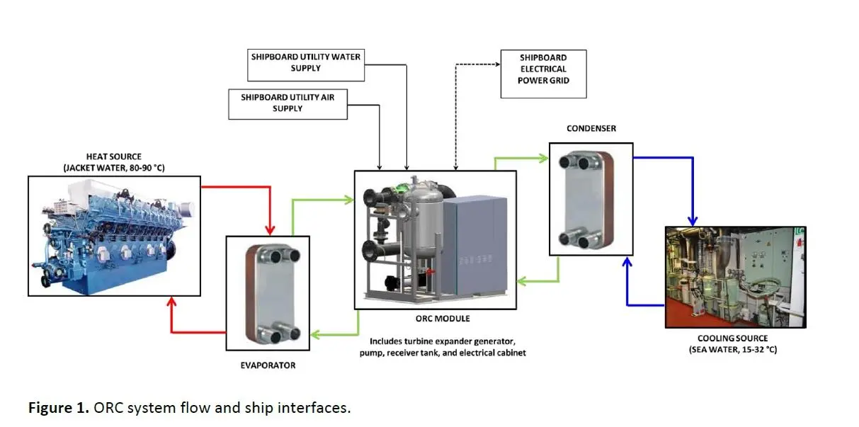
One of several recent developments in the promising field of waste hear recovery, the Hydrocurrent system uses an Organic Rankine Cycle (ORC) heat transfer process and a turbo-generator power conversion system to convert thermal energy from heat in the engine’s jacket water into mechanical power to generate electricity. Calnetix claims the system can produce up to 125kW of electrical power from a temperature source as low as 80⁰C. The result, the company says, is a saving of up to 200 tonnes of bunker fuel – reducing carbon monoxide emissions by 18 tonnes per year.
Calnetix – which has deployed over 35MW of capacity in land-based, industrial ORC installations over the past five years – reports that the system has been approved by ClassNK and Lloyd’s Register following extensive tests and inspections of the system’s turbo-generator, electrical, piping, controls and ORC components. The tests were witnessed by class surveyors and conducted in Calnetix’s manufacturing and test facilities in Cerritos, California. The final acceptance tests took place in March 2015.
A typical general cargo ship requires approximately 1MW of electrical power when underway. A modern LNG carrier may require power in excess of 12MW. Ship electrical power is typically provided by a combination of main engine-driven generators and auxiliary engine-driven generators. International maritime regulations require at least two generators as part of the ship’s main electrical system. Additionally, at least one generator needs to be independent of the speed and rotation of the main propellers and decoupled from the associated shaft.
Additional power generation capability can always be achieved by adding more generators via main or auxiliary engine generators. However, this adds significant operating cost, as well as adding to existing engine pollution. A better solution is to utilize the waste heat generated by the engines, to power a heat recovery cycle. Already, heat from engine exhaust is used on many ships for steam generation. To date, however, it has been difficult to extract heat from lower-grade heat such as the engine coolant.
The new technology aims to tap into the low-grade jacket water heat to generate additional electrical power without incurring any additional fuel usage. It is designed for use with ship engines ranging in size from 10 to 30MW output with a range of engine jacket water temperatures of 80 to 95⁰C, and with sea water cooling ranging from 10 to 32⁰C.
The Hydrocurrent system consists of a closed-loop ORC module, an integrated power module (IPM) and an electrical cabinet. The cycle begins with the liquid working fluid stored in a receiver tank at a pressure slightly above atmospheric and a temperature only a few degrees above sea water. The liquid is pumped to a higher pressure and circulated to an evaporator, where it vaporizes, absorbing heat from the engine jacket water. The pressurized vapour is then expanded through the IPM’s turbine which produces electrical power with its integrated generator. The working fluid is then cooled to a liquid state in the condenser, rejecting heat into sea water which is pumped overboard. The liquid working fluid is finally returned to the receiver tank to repeat the cycle.
The working fluid pump is of centrifugal multistage design and is mounted horizontally to aid in achieving compactness of the skid. A special feature of the pump is its low suction head, which accommodates particularly cold condensing conditions encountered in colder oceans. Driven by a variable frequency drive, the pump is capable of varying the cycle flow and pressure to compensate for varying heat source conditions and desired power generation settings.
Electrical power produced in the IPM is converted to meet the power quality and specification requirements of the ship. This is accomplished in an active converter within the Hydrocurrent unit. The electrical output power automatically synchronizes with the ship’s grid voltage and frequency and maintains this synchronization irrespective of ship grid fluctuation or heat source changes.
The IPM, a combination of a radial turbine and a Permanent Magnet (PM) generator, provides the means to convert pneumatic power into electrical power. The turbine and permanent magnets of the generator are integrated into a single rotor shaft and supported by active magnetic bearings.
This fundamental design feature brings numerous advantages over typical turbo-generators. The PM generator provides higher efficiency and smaller size over other types of generators. Magnetic bearings enable frictionless operation eliminating energy loss, wear and maintenance associated with otherwise lubricated bearings. And the integrated turbine and PM rotor eliminates a coupling and penetration between a turbine casing and generator eliminating associated mechanical shaft losses and working fluid leakage potential.
The integrated generator immersed in the working fluid flow eliminates a need for an external generator cooling system which reduces system cost and maintenance significantly. The turbine consists of a stationary nozzle and a radial wheel integrated into the rotor shaft. The turbine operates at an optimal speed of about 16,500rpm at a rated terminal power of 137kW. At the nominal pressure ratio of 3.0, the isentropic turbine efficiency (total to total) is about 90%. In addition, the turbine design accommodates off-design conditions with efficiency no less than 88.0% for pressure ratios ranging between 2.0 and 4.0.
The rotor is supported by five active magnetic bearings. The magnetic bearing design provides sufficient load capacity and load margin to ensure stable and robust operation under a variety of load sets. Sources of loading include the shaft weight, shaft unbalance, static offset (due to manufacturing variation), aerodynamic thrust and external vibration.
The electrical cabinet has three primary sections, housing power electronics, programmable logic and magnetic bearing controls as well as a power distribution unit. The power electronics (PE) system is a fully digitized motor controller with an active rectifier front end. It takes the variable, high-frequency power from the IPM generator and converts it to a regulated power that is synchronized to the ship’s grid.
The power of the IPM generator is converted from AC to DC then back again to match the grid voltage and frequency. The digital controls of the PE the speed of the IPM. Speed and temperature limits are programmed within the firmware. Requiring minimal cooling water (less than 30 L/min), the PE delivers up to 125kW of grid quality power at 440V AC/60Hz or 380V AC/50Hz with a conversion efficiency greater than 93% and a power factor 0.98 or greater. Total harmonic distortion (THD) of PE output power to the grid is no greater than 5% at 125kW.
The programmable logic controller (PLC) allows the ORC unit to operate autonomously. It monitors the temperatures and pressures necessary for proper operation as well as controls the automated engine jacket water and sea water source valves. Using temperature monitoring and the source valves the PLC ensures ship functions are unaffected when the ORC is offline. During operation, it also actively prevents the ORC from cooling the engine jacket water below 75⁰C or heating the sea water above 32⁰C in order to safeguard the operation of the ship’s fresh water maker.
The magnetic bearing controller (MBC) provides 5-axis control of the IPM’s active magnetic bearings. The MBC continuously monitors the rotor orbits and currents. Under adverse conditions, such as high levels of unbalance or vibration, the MBC sends a message to the PLC, and the ORC system is shut down in a controlled and safe manner.
The power distribution unit (PDU) is the point of interface to the ship’s electrical power supply. This section contains the necessary circuit breakers, contactors, filters and fuses to distribute power to the ship’s grid and ancillary ORC components.
Since the IPM’s generator uses the expanded working fluid as coolant, and the magnetic bearing system does not require any additional cooling, the entire IPM assembly is hermetically sealed. There are no rotating seals that require periodic maintenance. A hermetically sealed module together with non-wearing seals or bearings provides an inherently reliable, long lasting power module.
Factory testing
Several aspects of the ORC system are tested as individual components before the system assembly is completed. Further testing is done at the system level to ensure conformance to system level requirements. The IPM is comprised of the high-speed turbine expander together with the high-speed PM generator. The rotating assembly is supported on an active magnetic bearing system. Due to the complexity of this module and significance in determining the overall ORC system performance, a number of component level tests are conducted and validated against requirements.
The turbine expander magnetic bearing system is tested by levitating and spinning the IPM rotor independent of the overall ORC system. Using the MBC, the performance of the bearing system can be monitored and recorded. Furthermore, any changes to the compensator can be made at this time. Load capacity of the magnetic bearings is validated using a load cell.
The PE is also tested independent of the ORC system, whereby the active rectifier and inverter are tested to maximum load capacity and temperatures at the heat sink are monitored and recorded. Once these subassemblies have been tested and validated, the ORC system assembly takes place.
The system is then tested at the Calnetix ORC Test Facility, with representative heat source and condensing conditions. To validate turbine performance, the ORC system is operated at conditions which replicate engine jacket water using a closed loop of high pressure hot water.
In testing, the ORC is operated at several PE power output levels (between 50 and 125kW). The IPM is fitted with pressure and temperature transducers both before and after the turbine. In addition, condensing conditions are varied to change the turbine pressure ratio so as to generate a full map of turbine performance and efficiency data for validation against design analysis.
ORC and IPM performance are compared against design by measuring heat input from the hot water, working fluid flowrate, IPM turbine speed, IPM inlet and outlet conditions, generator and PE power outputs. From test measurements, the ORC gross efficiency is calculated as the quotient of PE power output to the rate of heat input from the hot water.
In the full power test, the cooling water temperature was maintained at 27⁰C and the ORC was operated to the maximum PE power output of 125kW. Test measurements reported (see table) are average conditions at steady state operation.
The total to total isentropic efficiency is very close to the design value and was calculated using the measured generator power output, IPM inlet pressure and temperature, and the wheel outlet pressure. Viscous rotor losses and generator efficiency correlations were used to arrive at the isentropic efficiency given these quantities were not measured directly. The system gross efficiency and IPM turbine isentropic efficiency are subject to a relative measurement uncertainty of less than 3%.