Creating the piston-free containership
Ultra large container vessels (ULCVs) need to adapt rapidly to a constantly changing economic environment. Transportation cost per TEU and the most economical way to meet new and future environmental rules on air pollution have become critical to operators on the main lines. Fuel representing the main source of air pollution and a great part of the cost, it is no surprise that many players are looking very seriously into LNG to satisfy compliance with new environmental rules and possibly reduce their fuel bill.
LNG as a fuel is ideal for gas turbines. By use of this clean fuel, the air temperature at the inlet of the turbine can be decreased and as a consequence the turbine efficiency can be increased compared to turbines fuelled with conventional ship fuel. At the same time the high temperature exhaust gases are used to produce steam in a waste heat recovery unit. This steam is used in a steam turbine which produces additional electric power, further increasing the overall efficiency.
For these reasons combined gas and steam turbine (COGAS) power generation today is the most efficient and economical way to convert fuel into mechanical power or electricity. Modern stationary COGAS plants running on natural gas reach net plant efficiencies of approximately 60%. This value cannot be reached by conventional two-stroke, slow-speed diesel engines of ships, where the engine efficiency is known not to exceed 52%.
The high power density and the modularity of COGAS plant together with electric propulsion concepts lead to additional container slots which contribute to the slots lost by the higher space requirements for LNG fuel storage compared to HFO storage.
The trend towards increasing size and relatively high design speeds of container ships lead to a high power demand for these ships. The COGAS principle associated with the right fractioning of power with a sufficient number of generators allows high efficiencies to be maintained for the whole range of power demand, making it competitive with conventional fuelled two-stroke diesel engine systems.
For these reasons GTT, CMA CGM (and its subsidiary CMA Ships) and DNV GL decided to have a closer look to the COGAS technology in order to evaluate its feasibility for application to container ships. For the feasibility study, Marine Assistance provided assistance for conceptual design of the ship and naval architecture, ARIAMIS for the thermal calculations of the glycol loop system, ABB for the electric propulsion system and Siemens for the COGAS power generation concept.
Reference ship
As a reference and base for the evaluation a conventional HFO-fuelled 19,000teu container vessel was used. The main design parameters are similar but not identical with the main design parameters of CMA CGM Marco Polo.
The most relevant design parameters used for the study are:
* 80MW total installed power
* Single screw layout
* 65MW at 22 knots at scantling draft
* Length overall: 400m
* Beam: 59m
* Depth: 33m
* Container capacity: 19,000teu
The analysis of overall ship efficiency and fuel consumption is based on an Asia-Europe roundtrip using the real profile and including all port calls. Electric power demand varies widely as a result of varying ship speed between the successive ports and different numbers of reefer containers carried. And of course there is a big difference between the power demand at sea, which reaches values of more than 50MW and the power demand in port, with less than 5MW.
The comparison of both designs is based on the total fuel consumption during the round trip. The final result showed that the overall efficiency of the COGAS system and the HFO-fuelled two-stroke main engine with four-stroke auxiliary engines and scrubbers are very similar. It has to be considered that the COGAS system that was chosen for the feasibility study is not finally optimised. There are still potential efficiency gains by:
* Minimizing the steam turbine size to increase efficiency;
* Reducing power capacities to run the system closer to the optimal efficiency;
* Optimising the condenser cooling of the steam turbine to increase steam turbine efficiency;
* Using a two-stage pressure steam turbine and steam generator;
* Improving design and efficiency of the combustion air cooling system.
It is expected that the net efficiency of the COGAS system will be well above the efficiency of the conventional system. Additional gains in efficiency are expected by optimising the ship design and taking more advantage of the flexibility related to the ‘missing’ engine room.
Design considerations
The most interesting principle of electrically propelled ships is disassociating generation from consumption of power. On such a ship all power consumers are electrically driven, including main propulsion.
Gas turbines for marine application are only available in relatively big power steps, narrowing the degrees of freedom to optimise the system in terms of installed power and load splitting for the given operational demands. However, especially for the gas turbine selection, it is essential to find the optimum balance between turbine sizes and number of installed devices for load fractioning (as gas turbine efficiency, compared to diesel engines, drops rapidly when running at low loads). In contrast to this, steam turbines typically are customised, giving the system designer high flexibility for optimization of the capacity of the Rankine cycle process.
Power sets and generation
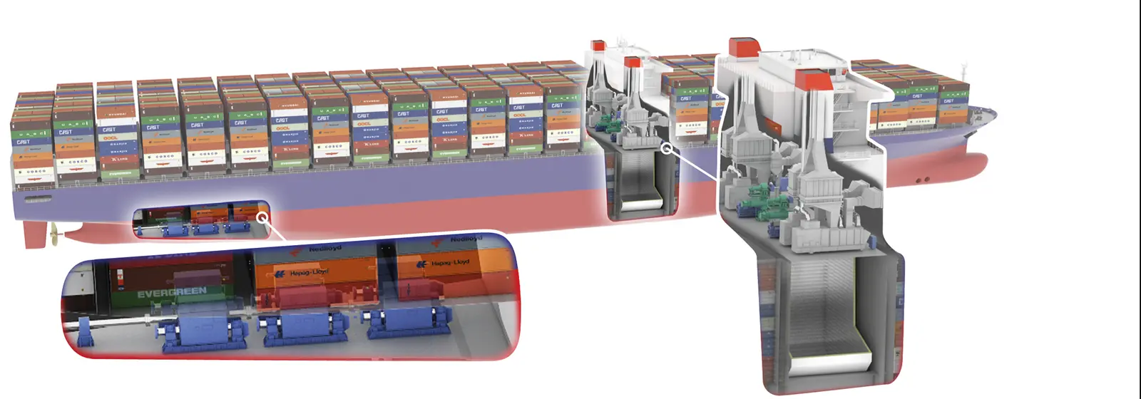
The proposed architecture for the ULCV features a symmetrical arrangement with a port and a starboard plant each consisting of two gas turbine driven electric generators with a capacity of 14.4MWe each and one steam turbine of up to 14MWe. Steam driving the turbines is generated by the two waste heat recovery units, each fitted in the exhaust gas piping of a gas turbine. For power generation in port, two dual-fuel four-stroke electric generators are installed having a maximum continuous rating (MC) of 2.77MWe and 4.15MWe.
The dissociation of electric generation from electric propulsion also allows locating the power plant away from the main propulsion. This is why the general arrangement of the ship shows minimum space for the propulsion room, which accommodates only the electric propulsion motors with associated systems (cooling, ventilation, transformers, power converters and resistances) and the shaft line. The electric power plant is merged with the accommodation in a single island located on top of the LNG storage tanks. The only connections from electric power plant to the propulsion room are power cables and the control monitoring bus network.
By design, the electric power generation plant (the heart of the ship power) is modular and fully redundant thanks to the symmetry introduced with nearly independent port and starboard systems, each of them using several electric generators.
Although there is only one shaftline, main propeller and rudder, there are three electric motors which can be run in fully independent mode providing a lot of flexibility and redundancy. This architecture may appear a bit complex but provides an extremely high level of reliability and safety. An FMEA study would easily demonstrate the superiority of such design in terms of power/propulsion availability as compared to a conventional mechanical drive.The single shaft arrangement is designed for 22 knots at scantling draft, requiring 65MW (Including 15% sea margin). Power is gearless, provided by three online identical slow-speed electric motors of 21.7MW each. Speed and torque from the electric motors can vary from extremely low to 100% capacity, stepless and with nearly no losses thanks to pulse width modulation (PMW) power converter units of type. The propulsion motor and power generating plant ensure high reactivity to ship acceleration and deceleration if running the electric motors in generator mode and dissipating the produced electric power. Further electric propulsion associated with large electric driven bow thrusters provide better response times and manoeuvrability than a slow speed two-stroke engine.
The PWM technology for electric propulsion is well proven and since the electric motors are slow speed online motors, gearboxes are not required. As compared to a conventional two-stroke slow speed main engine of this power, the electric motors are much more compact and can even be installed further aft on the shaft line in the shaft tunnel hence saving longitudinal space reducing substantially the room needed to install the propulsion.
Choosing the combined gas-steam cycle and electric propulsion drives gives additional freedom on the general arrangement. The LNG fuel tanks are located below the deck house which also integrates the gas as well as steam turbines at deck level. By doing so the aft structure of conventional 19,000teu design is minimized to accommodate only the electric propulsion motors. Additional container slots can be obtained within the former engine room of the conventional vessels. This results in one of the benefits of the COGAS system. While for “conventional” LNG fuelled ships one main drawback is the reduced cargo capacity due to the increased space demand of the LNG tanks if the same energy is stored as for an HFO-fuelled ship.
Considering further that the conventionally fuelled ship is expected to install scrubbers for meeting global sulphur cap as of 2020, space demands of these systems should be taken into account for a fair comparison. Further depending on the operational demands of the ship operator bunkering twice per roundtrip can be considered. This policy would allow for a halved tank capacity providing additional space in a significant amount. Utilization of this potential additional space would however require a rearrangement of the turbines.
Benefits of these two measures were not quantified and not taken into account within this study.
LNG supply and storage
The LNG is stored on board at cryogenic temperature (from -163°C to -155°C). To be used in the COGAS system, the LNG must be vaporized, pressurized and warmed up to ambient temperature. The flow has to be adjusted to the required power demand. These functions are performed by the fuel gas handling system consisting of LNG fuel pumps, LNG vaporizers, gas heaters, boil-off gas compressors and all associated regulating equipment, instrumentation and control/monitoring.
The power output and efficiency of gas turbine also depends on atmospheric conditions and in particular on temperature and humidity of the combustion air. In principle, the lower the combustion air temperature is, the higher is the power output and efficiency of the gas turbine itself.
Therefore it has been decided to use the combustion air of the gas turbines (flowing from outside through large air intakes) as the heating source to vaporize LNG and thereby recover during this vaporization the cooling power of LNG latent heat of vaporization. This process is achieved thanks to a dedicated glycol loop used as an intermediate heat carrying fluid. glycol is circulating in a fin-coil heat exchanger or similar placed in the air intake flow, hence cooling the air flow. The warmer glycol then gets in the LNG vaporizer and recovers the cooling power of the LNG during vaporization.
Two membrane fuel tanks are used for LNG fuel storage with the capacity of 10,960m³ each at 100% volume. They are fitted with GTT’s Mark III Flex Technology to ensure high thermal performance and can withstand any filling level. These tanks are located nearby midship section under the superstructure in lieu of HFO tanks for the oil fuelled design so that no commercial capacity is lost.
The tank pressure safety valves are set at 0,7barg, as per current level indicated in IGC and IGF codes. However, if need be, the scantling of the ship structure in way of the tank can be calculated to allow the tanks to operate at higher pressure which would facilitate bunkering operations.
For such volume on such a large vessel, membrane technology proves to be the most suitable and the most efficient LNG containment system.
Global strength
The innovative ship design, without an aft engine room island, is challenging as well the vessel strength. At DNV GL a global strength analysis has been performed. To do so a generic standard container ship design of about 20,000 TEU has been modified in the aft part by removing the machinery room and decks and adding lower engine room decks for the electric propulsion machinery space. On top of the deck, container spaces were considered within the hold. Main engine foundations of the piston engine have been replaced by smaller foundation for electrical propulsion motors.
The standard ship optimised structural design has to be reinforced at several local positions. This is mainly due to the reduced torsional stiffness of the new aft ship without the stiffing engine room construction. The diagonal hatch opening deflections resulted in higher, but controllable, values.
Cost benefit assessment
For the cost benefit assessment, investment cost of the PERFECt LNG fuelled ship was compared to the conventional propelled ship. Within the analysis, costs for additional and reduced systems to the base case where considered.
At this stage of the study, the capex for the COGAS ship are regarded to be 20-24% above a conventional fuelled vessel equipped with scrubbers. The opex costs largely depend on the difference in fuel price, the additional income related to the additional containers which can be transported and the savings related to possibly higher system efficiency.
At the time of closing this feasibility study (October 2015), the gas price in Europe on the spot market was nearly the same as the HFO price. By the end of March, the situation had further deteriorated for the business case since HFO prices have plunged to record low level. Even if gas prices have followed the same trend, the fixed cost of distribution infrastructure being higher than for conventional fuel, the price gap increases in favour of HFO and scrubber.
However this situation may not last (crude oil price may recover as quickly as it has plummeted) while LNG production is expected to stay above demand, maintaining downward pressure on gas prices. A business case using HFO plus scrubber as a reference therefore needs compensation either by a larger difference between HFO and LNG price or by additional benefits from efficiency improvement and additional revenue from additional container slots.
The results of the feasibility including the capex, opex and revenue calculations encourage the partners GTT, CMA CGM and its subsidiary CMA Ships and DNV GL to plan a more detailed evaluation of the overall system in a follow up project.
Conclusion
Main aspects for further optimization were identified in the study and comprise the aft hull geometry with other propelling alternatives, the process technology of the COGAS system including the steam turbine, and the available cooling capacity of the LNG as well as other aspects such as the business model for turbine acquisition and turbine maintenance.
Taking into consideration the identified potentials for optimization, the COGAS concept is expected to perform beyond the efficiency of the oil-fuelled engine systems used today. In the next step, the project partners GTT, CMA CGM and its subsidiary CMA Ships and DNV GL intend to work on the optimizationof the power supply system and of the overall ship design.