


More clarity needed on dry film thickness
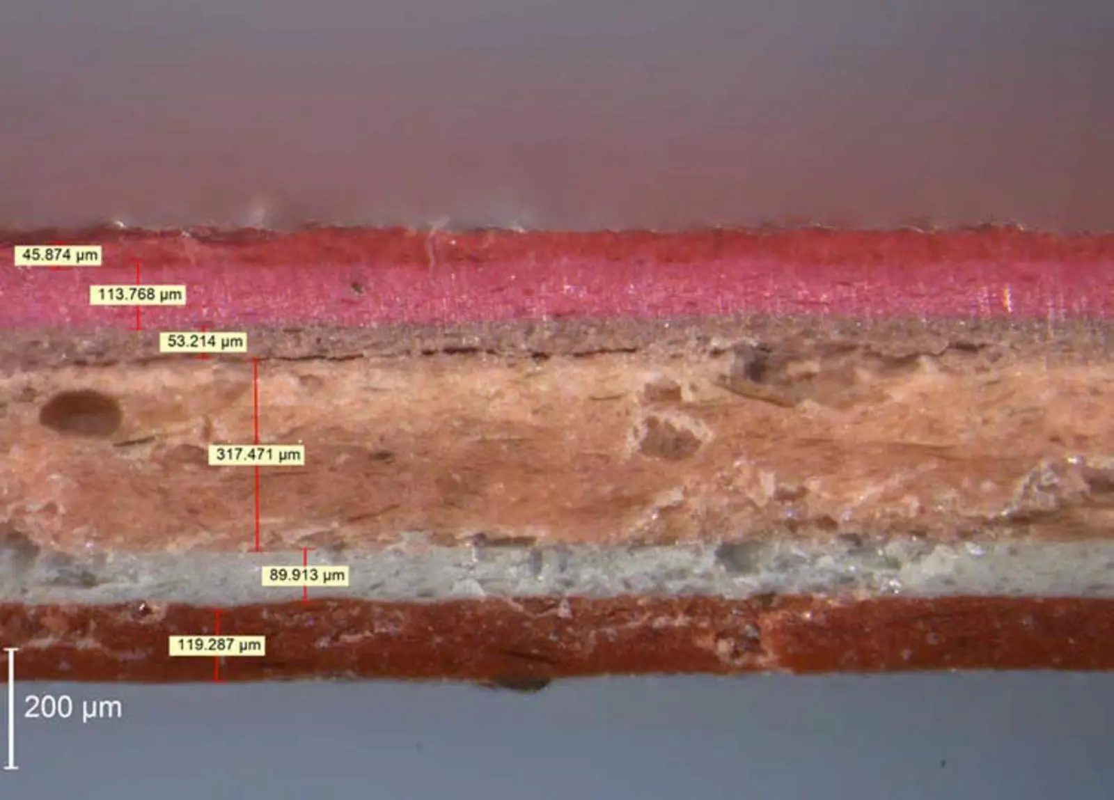
The IMO performance Standard for Protective Coatings (PSPC) introduced the concept of a minimum dry film thickness (DFT) based on the 90:10 rule, but this most basic aspect of the paint specification is neither well understood nor well specified. Its importance is clear, as a low DFT could lead to an increased chance of corrosion and a high DFT could lead to an increased chance of cracking.
DFT specifications are usually taken from the technical data sheet (TDS) for the product being used. The TDS normally provides a value or a range of values e.g. 125µm or 125-150µm and usually refers to a single coat. Thus if a scheme is 2 x 125µm, then the specified DFT is 250µm.
Control of DFT is dependent on many factors such as worker skill, equipment, access considerations and the complexity of the structure to be coated. Wind gusts, temperature changes and the size of the atomised coating particles are more examples of potentially important factors that can affect outcomes.
A hull coating could be specified as:
- 2x Epoxy anti-corrosive 250 µm
- 1x Modified epoxy 100 µm
- 3 x Self-polishing anti-fouling 390 µm
- Total scheme DFT 740 µm
In practice, it could be measured as.
- 2x Epoxy anti-corrosive 209 µm
- 1x Modified epoxy 317 µm
- 3 x Self-polishing anti-fouling 213 µm
- Total scheme DFT 739 µm
If this coating was assessed based on surface cleanliness and final DFT, it would most likely be accepted despite the low epoxy anti-corrosive and self-polishing anti-fouling layer thicknesses. Many of the major commercial shipyards’ procedures now only afford owners’ representatives the opportunity to assess cleanliness and final DFT as a standard procedure, so there is considerable opportunity for the as applied system to bear little or no relation to the specified scheme. This, combined with a total lack of as applied records (even with the presence of a coating technical file as required by the PSPC), results in considerable problems when trying to determine causes of a failure.
Often the key document used to determine the coating scheme is the TDS. A review of these documents for ballast tank coatings from the major paint suppliers reveals that the definition of DFT is not clear. Is it a minimum, a nominal, an average or typical value that is specified? What does typical mean? If it is a recommended DFT, how will performance of the coating change if the application deviates from the recommended value? What does any range given mean, is it a maximum/minimum or simply some guideline values?
When the paint specification only gives a value that says 2 x 160µm for example, what is this specified value? Is it the minimum, the mean, the mode or the maximum? To illustrate the potential for numerical variation, consider the numbers:
1,2,3,3,3,3,5,5,6,7,10,10
The mean is 4.83 and the mode is 3.00.
It would seem that most people would interpret the value given to be a nominal or an average (mean) value, i.e. it is not an exact number to be hit. It is understood that there will be variation with a good practice limit set by the guidelines and recommendations and a minimum set either by the physical ability of the paint film to coalesce or the adoption of a minimum rule such as the IMO 90:10 rule. However, we have come across inspectors (shipyard, owners and paint companies) that often consider it as a minimum value.
Most paint suppliers suggest that good practice would be that the maximum DFT should not be more than x2 that which is specified (per coat and for the whole scheme) with an allowance of up to x2.5 in limited areas (complex structural areas). In the absence of any such recommendations, ISO standards refer to a value of x3 the specified DFT, while for some yards, maximum DFT values are often specified as high as 2,000µm for ballast tank coatings (which is about six times the PSPC nominal DFT and way above the recommended guidelines of x2 the specified DFT). Clearly, it is easier for a shipyard to apply more paint to make up for low DFT than to remove paint in the event of excessive DFT.
The variability of the coating process, the number of coats of paint, the complexity of the surface and the interpretation of DFT often result in an average (mean) DFT far greater than that specified. The shift in the mean can be close to or exceed the x2 DFT maximum value that paint companies generally recommend as good practice.
Consider a specification of 2 x 160 µm as required by the IMO PSPC and as shown on most paint supplier data sheets. Good practice from paint company guidelines would give a maximum scheme of 2 x 320µm. Applying the 90:10 rule or the 80:20 rule would give minimum values of:
- 90:10 rule – 2 x 144 µm or 288µm total
- 80:20 rule – 2 x 128 µm or a 256µm total.
The standard deviation (a measure of the variation of sample measurements from the mean) for water ballast tank application has been derived at 162µm. Thus, if the minimum acceptable value is 288µm as per the IMO PSPC, then three standard deviations would provide a mean of 774µm [ given by: 288 + 3(162) µm] and the maximum value that could be expected would be 1,260µm [given by 774 + 3(162) µm].
The mean that is likely to be achieved will itself exceed the recommended guideline of most paint suppliers which is set at x2 the specified DFT (640µm in this case) and also surpasses the x3 value in ISO 12904. To achieve the required specification:
- Minimum 288µm
- Maximum 640µm
The standard deviation would have to be 58.7µm or about 36% of that being achieved in the field based on Safinah data.
The TDS provided by paint suppliers therefore needs to be very specific as to the DFT value that is being quoted. It is likely to be preferable to simply quote a range from the minimum to the maximum acceptable for each coat, rather than some vague value that could be interpreted as a minimum, a mean or some other measure such as nominal.
Paint suppliers would be prudent to test their products at expected DFTs that may be achieved in the field and provide data on the TDS for the elevated thickness expected. Thus the IMO PSPC specification may be better written as a range of 288µm to 640µm, this would imply a mean of about 464µm.
The problem is that it is clear that given the complexity of some aspects of ship structures, for the range to be practically achievable it must have a greater maximum, probably more like x3 the nominal value of 320µm, thus giving a range of 288 µm to 960µm. This would imply a mean of 624µm (assuming a normal, bell-shaped distribution of sample thickness measurements).
The introduction and use of minimum value rules in a specification (such as 90:10 or 80:20), will tend to increase the mean DFT excessively. The most significant of the variables in the coating process than can lead to this is the touch up process that takes the lower DFT values and increases them significantly (to the right of the mean on a bell curve) by the addition of more paint through brush or spray application. This will tend to skew the usual bell-shape distribution towards the right, meaning more samples of high DFT will be encountered. In practice, we have found that DFT data is often skewed in this way.
DFT gauges are set up to assume that the readings being collected are represented by a normal, bell-shaped distribution and provide statistical results based on this assumption. As DFT readings for a ship tend to fall into a skewed distribution, it raises concerns about how the data from gauges is summarised and presented. However, if instead of taking individual readings, three readings are taken for a spot measurement, the problem will be reduced as the samples will tend to conform to the assumed bell-shape distribution.
What should be taken away from this study is that the way that coatings are currently specified is inadequate, and that how the DFT is provided on the TDS can be quite misleading. It is recommended that the TDS should simply contain a maximum and minimum value for DFT rather than some individual ambiguous value. This would leave each paint supplier to determine the DFT range over which their products will provide the claimed performance. This would add some complications. For instance, drying times, cure times and other data that may be affected by DFT (such as time to service) will need to reflect the range that is provided.
Those developing coating specifications should also consider the range of DFT as more important than a specific DFT value (nominal, mean or otherwise). The range would then reflect any minimum/maximum values recommended by the paint supplier. The challenge will be to achieve a range that is achievable by the application process.
Given a range of DFT to hit, the obvious question will be: what if some few points are outside the range either way, what is acceptable? We are of the view that the range on the TDS should define the absolute minimum and maximum for various end service uses for any given product.
The problem with ships in particular is even if you accept 1% or 2% of the readings to be outside the range provided; the total area equating to such a small percentage may cover can still be quite large. For example, 5% of 30,000m² of cargo hold would mean that 1,500m² would be outside the range. This is not an insignificant area.
It is clear therefore that variability should be minimised and technical documentation needs to better reflect the in-service practicalities.